


 Current position > News detail
『Blowby Flow Meter: Engine Crankcase Ventilation Leakage Diagnostic Tools』Related information(flow rotameter|digital flow meter|balo meter|hydraulic flow meter|volumetric meter|positive displacement meter|pitot tube flow meter|displacement meter|cfm meter|variable area flow meter|inline flow meter|differential pressure flow meter|calibrated flow meter|velocity meter|paddle wheel flow meter|oval gear flow meter|anemometer hvac|multiphase flow meter|doppler flow meter|thorpe tube flowmeter|heat flow meter)

Blowby Flow Meter: Engine Crankcase Ventilation Leakage Diagnostic Tools
Quick Answer: A blowby flow meter measures the volume of combustion gases that leak past piston rings into the crankcase. Monitoring this flow continuously helps maintenance teams catch ring wear, cylinder scoring, and turbo seal failure long before a forced outage. Silver Automation Instruments supplies thermal mass flow meters and DP-based insertion probes for blowby flows from 0.5 Nm3/h up to 500 Nm3/h on stationary gas engines, marine diesels, and backup generators.
Here is the thing: a 0.5 Nm3/h increase on a 1 MW gas engine can shift the overhaul schedule by thousands of hours. Power plant operators in Nigeria and the Philippines install continuous blowby meters to avoid unplanned stops that cost over 25,000 USD per day.
What Blowby Flow Really Tells You
Blowby flow is not just a nuisance number. It correlates directly with combustion chamber sealing. When piston rings wear, the clearance gap widens and more combustion gas escapes into the crankcase before the exhaust valve opens.
On a medium-speed diesel engine running on heavy fuel oil, a sudden jump from 15 Nm3/h to 22 Nm3/h often points to a broken ring or a scuffed liner. A slow drift upward over six months usually indicates normal ring groove wear. Most engineers skip this separation. They check crankcase pressure with a manometer and call it good. In practice, a thermal mass blowby meter shows the trend days or weeks before the pressure alarm triggers.
Which Flow Meter Technology Works for Crankcase Ventilation
Two measurement principles dominate the market: thermal mass flow and differential pressure across an orifice. Thermal mass meters measure gas mass flow directly without needing separate temperature and pressure compensation. This is a big advantage on engines where crankcase gas temperature swings from 40 °C to 110 °C.
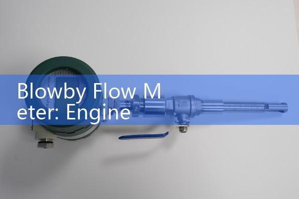
Silver Instruments offers an inline thermal mass flow meter with 4-20 mA HART output and ATEX Zone 1 certification. The sensor element resists oil mist coating better than a hot-wire anemometer. For large crankcase vent pipes from DN25 to DN50, an insertion version with a PT100 reference sensor gives stable readings even with pulsating flow. A condensation trap upstream prevents oil slugs from hitting the sensor. Pipe fittings are available in 316L stainless steel for marine environments.
Blowby Flow Meter vs. Crankcase Pressure Sensor
Pressure sensors are cheap and simple. But they respond late. Crankcase pressure stays almost flat until blowby flow exceeds the breather capacity. By the time the pressure spike appears, the damage is often done.
A flow meter catches a 20 % rise in blowby gas volume right away. A biogas plant in Thailand runs six Jenbacher J420 engines and uses our insertion flow meters to trend blowby on a Modbus SCADA channel. The operations manager told us the flow data gives him at least 72 hours of early warning before oil carryover b
Real-World Example: A Marine Auxiliary Engine in Singapore
Last year a ship operator approached us with a 2,500 kW auxiliary diesel engine that showed rising scavenge air pressure and heavy lube oil consumption. They needed a blowby meter that could work in a hot engine room with 90 % humidity and occasional oil mist.
We recommended a thermal mass insertion flow meter with a remote transmitter and ATEX/IECEx approval. The crew installed it on the vent line DN40 pipe during a short port stay. Within ten days, the meter logged a blowby flow of 18 Nm3/h while the OEM limit at full load was 12 Nm3/h. They scheduled a piston ring replacement at the next port call and avoided what the chief engineer estimated as 45,000 USD in downtime and oil cleanup.
Installation Points That Save Field Time
Mount the meter on a straight pipe run, at least 10 diameters downstream and 5 diameters upstream of any elbow or valve. If the vent line carries heavy oil mist, place a drip leg or coalescing filter before the meter.
In engine rooms where ambient temperature reaches 55 °C, use a remote transmitter separated from the sensor. We have seen many customer sites in the Middle East where a direct-mounted transmitter failed because heat soak drifted the electronics. A remote model with a stainless steel junction box solves this.
Frequently Asked Questions
What is a normal blowby flow for a diesel engine?
Typically 0.5 to 2 percent of the intake air mass flow. A 500 kW diesel may show 2 to 6 Nm3/h. Anything above 5 percent of intake flow calls for immediate inspection.
Can a blowby flow meter detect turbocharger seal leaks?
Yes. A sharp rise in blowby combined with blue exhaust smoke often indicates a turbo oil seal failure. The flow meter reveals the problem hours before the smoke becomes obvious.
Does Silver Instruments supply ATEX and IECEx certified meters?
We ship thermal mass flow meters with ATEX and IECEx certification for Zone 1 and Zone 2 areas. The sensor head is flameproof EEx d, and the transmitter can be mounted in a safe area or inside a purged cabinet.
What output signals do your blowby flow meters provide?
Standard models include 4-20 mA HART, pulse, and RS485 Modbus RTU. You can feed the signal to an engine control panel, a PLC, or a remote telemetry unit.
What details do you need to quote a blowby flow meter?
Send us your engine displacement and power, the expected blowby flow range, pipe diameter (DN), gas temperature, and hazardous area classification. We will propose a suitable meter and send a datasheet within one business day.
Request a Blowby Flow Meter Specification and Price
Tell us your engine data and operating conditions. Contact Silver Automation Instruments directly.
Email: [email protected]
Tel: +86-135-1213-1526
WhatsApp: 86-135-12131526
WeChat: +86 13512131526